Search
Reactive power controller for the DIN rail

multicomp D6

Reactive power compensation components
multicomp D6 multicomp TFT freigestellt

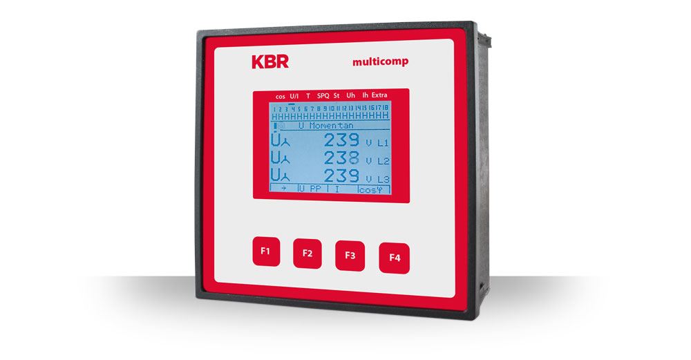
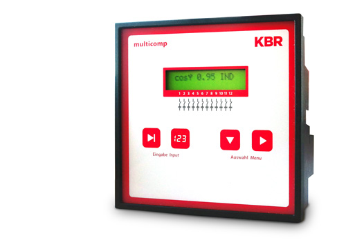
The multicomp D6-xxx-7 reactive power controller is the measuring and control unit for reactive power compensation systems.

The reactive power controller developed and manufactured in Schwabach works automatically in 4-quadrant operation (generator operation), i.e. even when feeding back into the utility grid, missing compensation power is easily detected and compensated. This is particularly important in view of the increase in companies’ own generation systems, e.g. biogas or PV systems.

To protect the capacitors from overvoltages, overcurrents and excessive harmonic loads, the reactive power controller has grid analysis and limit value monitoring functions. In addition, the integrated temperature measurement input monitors the ambient temperature in the compensation system and switches on the fan if a specified limit temperature is exceeded. You can also expand the controller with the secureC safety and maintenance module.

The multicomp D6 reactive power controller also has an interface for connection to the KBR eBus, allowing all settings to be made conveniently from a PC. Bus communication can also be switched from KBR eBus to Modbus RTU/ASCII.

Highlights
Technical data
  • Fast control behavior due to simultaneous switching of several stages
  • Extended mode for generation systems (EZA mode) by selecting different Q controls: Q[U], Q[P], Q[AI], Q[DI (max. 16 digital inputs)]
  • Remote main current measurement (using multimess D4-1) incl. Summation of several measuring points to a total Cos-Phi
  • Recognizing and compensating for the missing compensation power even when feeding back into the utility grid
  • Mains analysis and limit value monitoring function to protect capacitors from overvoltages, overcurrents and excessive harmonic loads
  • Indication via LC display, stage status and regeneration
  • Integrated temperature measurement input for monitoring the ambient temperature and for switching on the fan if the limit value is exceeded
  • Modular up to 24 steps
  • Prepared for the control of an analog compensation stage
  • Available in two language packages: DE/EN/FR or EN/ES/PT
Measuring accuracy
Electricity ± 0.5 % / ± 1Digit
Tension ± 0.5 % / ± 1Digit
Services ± 1 % / ± 1Digit
Power factor ± 2 % / ± 1Digit
Frequency ± 0.1 Hz / ± 1Digit


Device memory
Working,
Data & parameter memory
2 MB Flash
Program memory 512 kB Flash
Memory type Ring buffer
Extreme values (max./min.) The maximum values that have occurred since mains connection or manual extreme value deletion (drag indicator function) with date and time
Event memory Memory capacity, 1500 entries with date and time of occurrence
Operating logbook Memory capacity, 500 entries with date and time of occurrence
Limit violations Detection time ≥ 200 ms
Voltage dips in the measurement voltage Detection time ≥ 20 ms; threshold adjustable via PC, default after reset 85% of nominal voltage (according to EN61000-4-30).


Measuring principle
Scanning 64 measured values per period
A/D converter 12 bit
Measurement of U and I Simultaneous measured value acquisition for U and I measurement
Update speed (complete measurement cycle) ~ 330 ms
Calculation of harmonics FFT with 64 points over one period
Frequency measurement Reference: Voltage measurement between phase Lx – N / Ly); correct frequency measurement through grid tracking


Power supply
Power supply US1: 100-240V ± 10% DC/50/60Hz
Power consumption 22VA


Hardware inputs
Measurement input for voltage Terminals 10 and 13: 57.75V… 500V…600V AC, designed for max. 500V AC nominal voltage, over 500V AC PH-PH up to 30.00KV AC PH-PH with voltage transformer attachment
Input impedance: Min. 2.5 MOhm
Measuring range: programmable
Temperature input Terminals 51 and 52: Connection for PT1000 sensor
Measuring range: -20°C to 100°C ± 2°C
Measuring input for current Terminal 20 and 21:

0.05A…5A…6A AC (with x/5A converter), designed for max. 5A AC rated current
0.01A…1A…1.2A AC (with x/1A converter), designed for max. 1A AC rated current

Power consumption:

0.3 VA per input at 6 A,
0.05 VA per input at 1.2 A

Measuring range: programmable


Hardware outputsa
Relay outputs Switching stages: 5 on the basic device, 1 of which can be configured as a fan
Switching capacity: 250V (AC) / 2A per relay
Fault signal relay Switching capacity: 250V (AC) / 2A potential-free, configurable as fan or switching stage
Interface Serial interface: RS-485
Bus protocol: KBR-EnergieBus / Modbus
Transmission speed: 38400 baud, with Modbus selectable 4800, 9600, 19200 baud
Addressing: Addressable up to addr.9999 for KBR eBus, scan mode can be activated on the device
Bus addresses for Modbus 1 to 247 can be set on the device
Display and configuration interface Serial interface: RS-485 (RJ12)
Module bus interface Serial interface: RS 485 (RJ12) for pre-assembled KBR system cable (modular cable 6-pin, unshielded) max. Length 30 m with suitable installation


Electrical connection
Connecting elements Plug-in terminals
Permissible cross-section of the connecting cables 2.5 mm2 (bus connection and temperature sensor 1.5 mm2)
Measuring voltage inputs Fuse protection: max. 1 A slow or max. C2-Automat,max. 1 A slow or max. C2-Automatic, additionally mains disconnecting device approved according to UL/IE
Measuring current input Fuse protection: NONE!!! – Current transformer terminals k and l before the
Always short-circuit when opening the circuit!
Control voltage input Fuse protection: max. 1 A slow or max. C2-Automat,max. 1 A slow or max. C2-Automatic, additionally mains disconnecting device approved according to UL/IE
Relay output Fuse protection: max. 2A medium yields
BUS connection Connection material: For correct operation, only use shielded and twisted-pair cables; e.g. J-Y(St)Y EIB 2x2x0.8
Converter connection Wiring: see connection diagram multicomp (123 KB)
BUS connection Connections for BUS – connection via RS-485
Terminal 90 (⊥) →Pin ⊥→
Terminal 91 (A) →Pin A →
Terminal 92 (B) →Pin B →


Mechanical data
DIN rail device
Housing dimensions 90 x 106 x 61 mm (H x W x D)
Mounting type Wall mounting on standard rail 7.5 mm deep, in accordance with DIN EN 50022)
Weight approx. 650 g


Ambient conditions / Electrical safety
Ambient conditions Standards: DIN EN 60721-3-3/A2: 1997-07; 3K5+3Z11; (IEC721-3-3; 3K5+3Z11)
Operating temperature: K55 (-5°C …. +55°C)
Humidity: 5 % … 95 %, non-condensing
Storage temperature: K55 (-25°C …. +70°C)
Operating altitude: 0….2000m above sea level
Electrical safety Standards: DIN EN 61010-1: 2011-07
Protection class: I
Overvoltage category: CAT III
Rated impulse voltage: 4 kV
Protection class Standards: IP20 according to DIN EN 60529: 2014-09
EMC Standards:
DIN EN 61000-6-2:2006-03 + Corrigendum 1:2011-03
DIN EN 61000-6-3:2011-09 + Corrigendum 1:2012-11
DIN EN 61326-1:2013-0
Fittingly:
multicomp-f144-3ph_perspektive-ci-neu_

Reactive power controller 3-phase

multicomp-f144-3_

Reactive power controller 1-phase

KBR
Support Team

We are happy to arrange
the contact to our
references and are available for
available for an interview.

Just get in touch with us.
Phone: +49 9122 6373-0
E-mail: info@kbr.de

Tablet mit Screenshot

Download

More information (brochures, user manuals, etc.) under download.